ESAB MIGMASTER 250 Bedienerhandbuch
Stöbern Sie online oder laden Sie Bedienerhandbuch nach Schweißsystem ESAB MIGMASTER 250 herunter. ESAB MIGMASTER 250 Instruction manual Benutzerhandbuch
- Seite / 60
- Inhaltsverzeichnis
- LESEZEICHEN
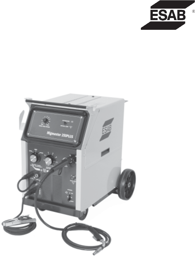
- MIGMASTER 250 Plus 1
- USER RESPONSIBILITY 2
- TABLE OF CONTENTS 3
- SECTION 1 SAFETY PRECAUTIONS 5
- §25249.5 et seq.) 8
- SECTION 2 DESCRIPTION 11
- SECTION 3 INSTALLATION 17
- SECTION 4 OPERATION 29
- SECTION 5 MAINTENANCE 39
- 0558003218 44
- 0558003217-B 45
- 0558004117 46
- 0558004116 47
- SECTION 6 REPLACEMENT PARTS 49
- CIRCUIT 53
- DESIGNATION 53
- REVISION HISTORY 59
- F15-728-D 09 / 2007 60
- Hours: 7:30 AM to 5:00 PM EST 60
Inhaltsverzeichnis
MIGMASTER 250 PlusWELDING PACKAGESF15-728-D 09 / 2007INSTRUCTION MANUALThis manual provides complete instructions for the followingpower sources start
10levage, des câbles de grue ou divers cheminsélectriques.g. Empêchez l’apparition de toute humidité, notammentsur vos vêtements, à la surface de l’em
11Industrial Ready-To-Weld Mig PackageMigMaster 250 Plus Rated 250 amps at 50% duty cycle DC welding output from 30 to 280 amps 24 overlapping heat
12Table 2.2 - GunMaster-250 Torch AccessoriesWire Contact Tips LinersSize & Type Short (S) Medium (M) Long (L) 10' 12' 15'Hard Wire
132.1 GENERALThis manual has been prepared especially for use in familiarizing personnelwith the design, installation, operation, maintenance, and tro
14SECTION 2 DESCRIPTION2.3 DESCRIPTIONThe Migmaster 250 Plus is a portable compact welding system designed forfine wire, (.023, .030, .035 and .045 in
152.4 OPTIONAL ACCESSORIES2.4.1 SPOT/STITCH/ANTI-STICK MODULE, P/N 0558003239This easy-to-install, plug-in module mounts inside the feeder compartment
16SECTION 2 DESCRIPTION2.4.3 ST-23A SPOOL-ON-GUN TORCH, P/N 19164 (see F14-353)The Migmaster 250 Plus unit is equipped with a built-in control for the
17III. INSTALLATIONThis manual has been prepared for use by an experienced operator. It providesinformation to familiarize the operator with the desig
18It is recommended that a line discon-nect switch be installed in the inputcircuit to the welding machine. Thiswould provide a safe and convenientmea
19SECTION 3 INSTALLATIONFigure 3.2 Input Voltage Change-Over Connections for the 208/230 Vac Model230Vac Tap Connection to theON/OFF Switch Pigtail(Fa
2BE SURE THIS INFORMATION REACHES THE OPERATOR.YOU CAN GET EXTRA COPIES THROUGH YOUR SUPPLIER.These INSTRUCTIONS are for experienced operators. If yo
20SECTION 3 INSTALLATIONFigure 3.3 Change-Over Connections Exposed 208/230 Vac ModelFigure 3.4 Input Voltage Change-Over Connections for the 208/230 V
213.4.2 CHANGE-OVER for the 208/230/380/400/460/575 Vac ModelFigures 3.5.a-f show how to reconfigure the "multi-voltage" model from thefac
22SECTION 3 INSTALLATION3.5 SECONDARY OUTPUT CONNECTIONSThe Migmaster 250 Plus Welding System is a completely self-containedwelding system that featur
23SECTION 3 INSTALLATIONSelecting the proper Inductance for a specific application and shield gas ismostly a matter of personal preference. The Induct
24GunmasterReceptacleTrigger LeadReceptacleSpool Gun ControlCable ReceptacleGunmasterRetaining ScrewSECTION 3 INSTALLATIONSpool RetainingClipSpool Bre
25SECTION 3 INSTALLATION3.8 WIRE FEEDER MECHANISM3.8.1 DRIVE ROLLSThe drive roll has two grooves: the small groove feeds 0.035 in. diameter wire,the l
26As with any work area, make sure safetyglasses with side shields are worn whenhandling or changing wire or clippingwire off at the spool or at the e
27SECTION 3 INSTALLATIONE. Attach the regulator to the cylinder valve, tighten the union nut securelywith a 1-1/8in. open end or an adjustable wrench.
28SECTION 3 INSTALLATION
294.1.1 POWER SWITCHA line toggle switch on the front panel energizes the primary of the maintransformer. This switch also turns on the fan, which is
3SECTION NO. ... PAGE NO.
30SECTION 4 OPERATION4.1.2 VOLTAGE CONTROL (Coarse Range Selector and Fine AdjustmentRange Selector)Voltage control is by means of two high current ta
31SECTION 4 OPERATION4.2 OPERATING PROCEDURES4.2.1 OPERATING SAFETY PRECAUTIONSComply with all ventilation, fire and other safety requirements for arc
32E. Spool of correct size wire is locked in place, brake tension is set, and wireis properly threaded through the inlet guide to the gun tip.F. The w
33Figure 4.2 - Angle of Welding Wire with JointThis equipment is provided with a thermostat (OL) in the transformer (T1)windings which will open and p
34SECTION 4 OPERATIONTable 4.1 Weld Setting
35SECTION 4 OPERATION4.5 SPOOL-ON-GUN CONNECTION/OPERATIONThe Migmaster 250 Plus is equipped with a built-in control for the ST-23A or MT-250SG Spool
364.6 OPTIONAL SPOT/STITCH/ANTI-STICK CONTROL MODULEThis optional control module allows the operator to use the 250 Plus for Spotor Stitch or Continuo
37SECTION 4 OPERATION4.6.3 SPOT WELDING MODE OPERATIONA. Place the three-position toggle switch in “Spot” position.B. Replace the standard nozzle with
38SECTION 4 OPERATION
39SECTION 5 MAINTENANCE5.1 MAINTENANCEShut OFF shielding gas supply at source.To aid in checking and servicing, use Schematic, Figure 5.1.5.2 INSPECTI
4TABLE OF CONTENTS
40SECTION 5 MAINTENANCEIf it should become necessary to re-place this or any other fuse in the weld-ing machine, ensure that the proper sizefuse is us
41SECTION 5 MAINTENANCEMany troubleshooting situations requirethat the power remain On and that powerterminals in the equipment carry volt-age. Exerci
42SECTION 5 MAINTENANCETABLE 5.1 TROUBLESHOOTING GUIDEWELD CONDITION POSSIBLE CAUSE REMEDY1. No weld or control power. a. Primary input power not avai
43WELD CONDITION POSSIBLE CAUSE REMEDYSECTION 5 MAINTENANCE10.Shield gas flow low or a. Cylinder valve closed. a. Turn off regulator, slowly openstopp
44Figure 5.3 - Wiring Migmaster 250 Plus for 208/230V Model0558003218SECTION 5 MAINTENANCE
45SECTION 5 MAINTENANCEFigure 5.4 - Schematic Migmaster 250 Plus for 208/230V Model0558003217-B
46SECTION 5 MAINTENANCEFigure 5.5 - Wiring Migmaster 250 Plus for 200 - 575V Model0558004117
47SECTION 5 MAINTENANCEFigure 5.6 - Schematic Migmaster 250 Plus for 200 - 575V Model0558004116
48SECTION 5 MAINTENANCE
49SECTION 6 REPLACEMENT PARTSA. REPLACEMENT PARTSWhen ordering replacement parts, order by part number and part name, as illustrated on the figure. A
5WARNING: These Safety Precautions are foryour protection. They summarize precautionaryinformation from the references listed in Addi-tional Safety In
50FIGURE 6.1 - MIGMASTER 250 PlusSECTION 6 REPLACEMENT PARTS7961641011812131518191720123514
51SECTION 6 REPLACEMENT PARTSITEM NO. QTY. PART NUMBER DESCRIPTIONCIRCUIT DESI GNAT I ON0558003215 Migmaster 250, 208/230Vac (console only)0558003216
5232343533313236SECTION 6 REPLACEMENT PARTSFIGURE 6.2 - MIGMASTER 250 Plus (Front)383739434041424430
53SECTION 6 REPLACEMENT PARTS46505147454948FIGURE 6.3 - MIGMASTER 250 Plus (Rear)ITEM NO. QTY. PART NUMBER DESCRIPTIONCIRCUIT DESIGNATION30 2 950396
54FIGURE 6.5 - MIGMASTER 250 Plus Main Assembly (Left Side)SECTION 6 REPLACEMENT PARTSFIGURE 6.4 - MIGMASTER 250 Plus Main Assembly (Right Side)5354
55SECTION 6 REPLACEMENT PARTS63646665FIGURE 6.6 - MIGMASTER 250 Plus Electronics CompartmentITEM NO. QTY. PART NUMBER DESCRIPTIONCIRCUIT DESIGNATION5
56SECTION 6 REPLACEMENT PARTSFigure 6.7 - Feeder Compartment74717976818280FIGURE 6.8 - MIGMASTER 250 Spool Spindle Assenbly727573ITEM NO. QTY. PART N
57SECTION 6 REPLACEMENT PARTS83
58SECTION 6 REPLACEMENT PARTSFigure 6.9 - Auto-Lift Mini Four Roll Geared Wire Drive System - 055800133911A234567891011121314ITEMITEMPART NO.15161718
591. The "A" revision of this manual updates the replacement parts section and wiring/schematic diagramsthroughout this manual. Various edit
6FUMES AND GASES -- Fumes andgases, can cause discomfort or harm,particularly in confined spaces. Donot breathe fumes and gases. Shield-ing gases can
F15-728-D 09 / 2007ESAB Welding & Cutting Products, Florence, SC Welding EquipmentCOMMUNICATION GUIDE - CUSTOMER SERVICESA. CUSTOMER SERVICE QUE
7ADVERTENCIA: Estas Precauciones de Seguridadson para su protección. Ellas hacen resumen deinformación proveniente de las referencias listadasen la s
8HUMO Y GASES -- El humo y los gases,pueden causar malestar o daño,particularmente en espacios sinventilación. No inhale el humo o gases.El gas de
9a. Éloigner suffisamment tous les matériaux combustiblesdu secteur où l’on exécute des soudures ou descoupes à l’arc, à moins de les recouvrir compl
Weitere Dokumente für Schweißsystem ESAB MIGMASTER 250


© 2020, manymanuals.de. Alle Rechte vorbehalten. | 0.652 s |
 Manymanuals.com
 Manymanuals.de
 Manymanuals.fr
 Manymanuals.it
 Manymanuals.pl
 Manymanuals.cz
 Manymanuals.es
 Manymanuals-pt.com
Kommentare zu diesen Handbüchern